The C4 model is used to visually represent a system’s architecture and explain how it is decomposed into elements. Diagrams in this model are organized according to increasing levels of scale and detail:
-
Level 1: Context diagram. Shows the system within its external context: user roles and other systems that directly interact with it.
-
Level 2: Container diagram. Breaks the system down into containers (major subsystems) and shows the main interaction paths between them. In the C4 model, a container (not to be confused with Docker containers) is an executable and deployable subsystem, such as an executable file.
-
Level 3: Component diagram. Breaks each container down into components and shows interactions between components (within a single container) and with other containers. In the C4 model, a component is a software module (subsystem) within the container’s codebase. This level is described in the architectural diagrams of individual services.
-
Level 4: Code diagram. Describes the code elements that implement the components.
Due to the large number of elements at Level 2, the complete container diagram is not shown here. Instead, the following intermediate diagrams are provided after the Level 1 diagram:
Level 2 and higher diagrams are provided in the sections describing the architecture of individual modules.
To get a general understanding of the Deckhouse Kubernetes Platform (DKP) architecture, it is sufficient to review the Level 1 diagram as well as the subsystem and module diagrams. For a detailed view of individual services, refer to the Level 2 and higher diagrams available in the relevant sections.
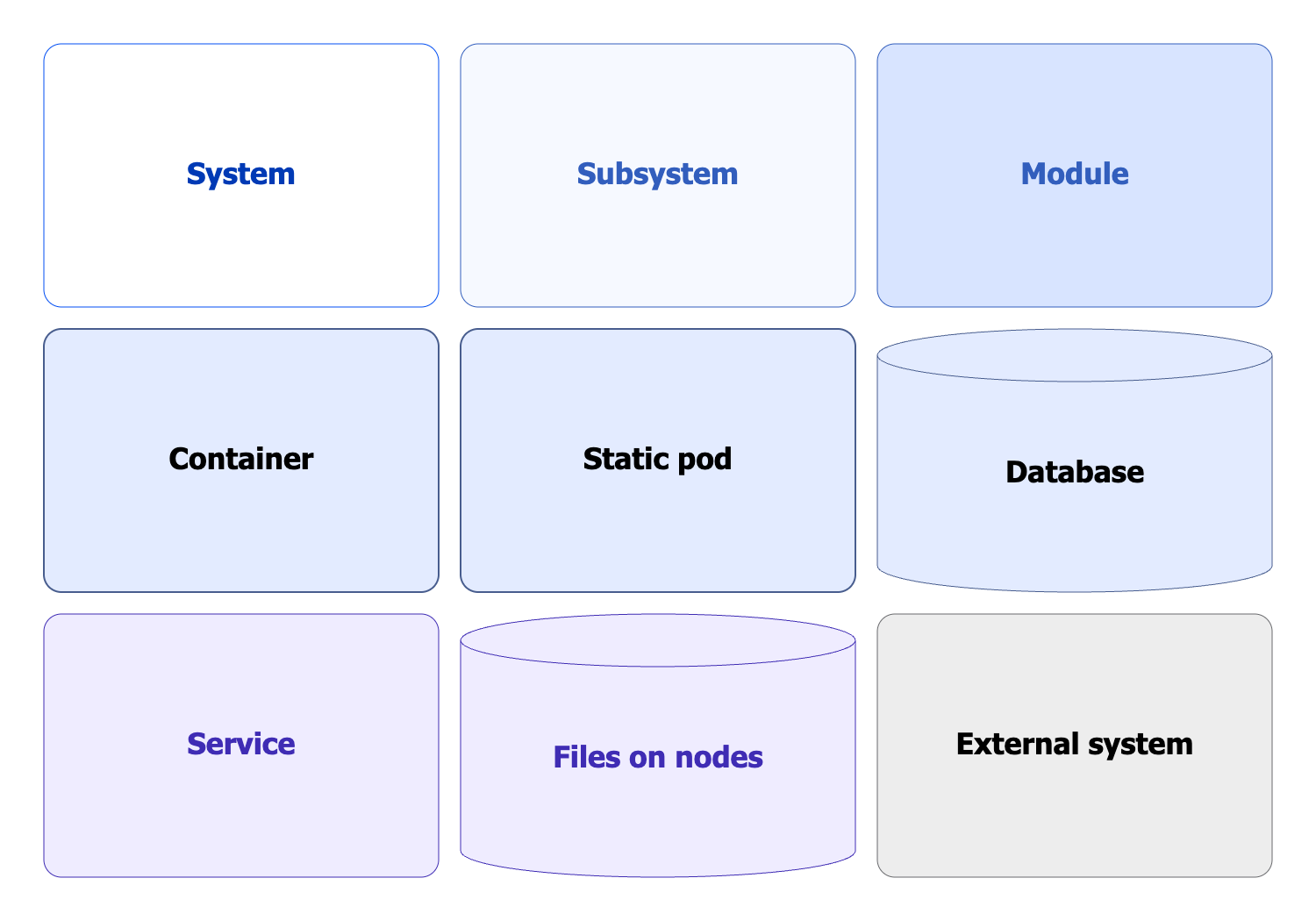
Legend
The following graphical symbols are used in the diagrams:
Context diagram
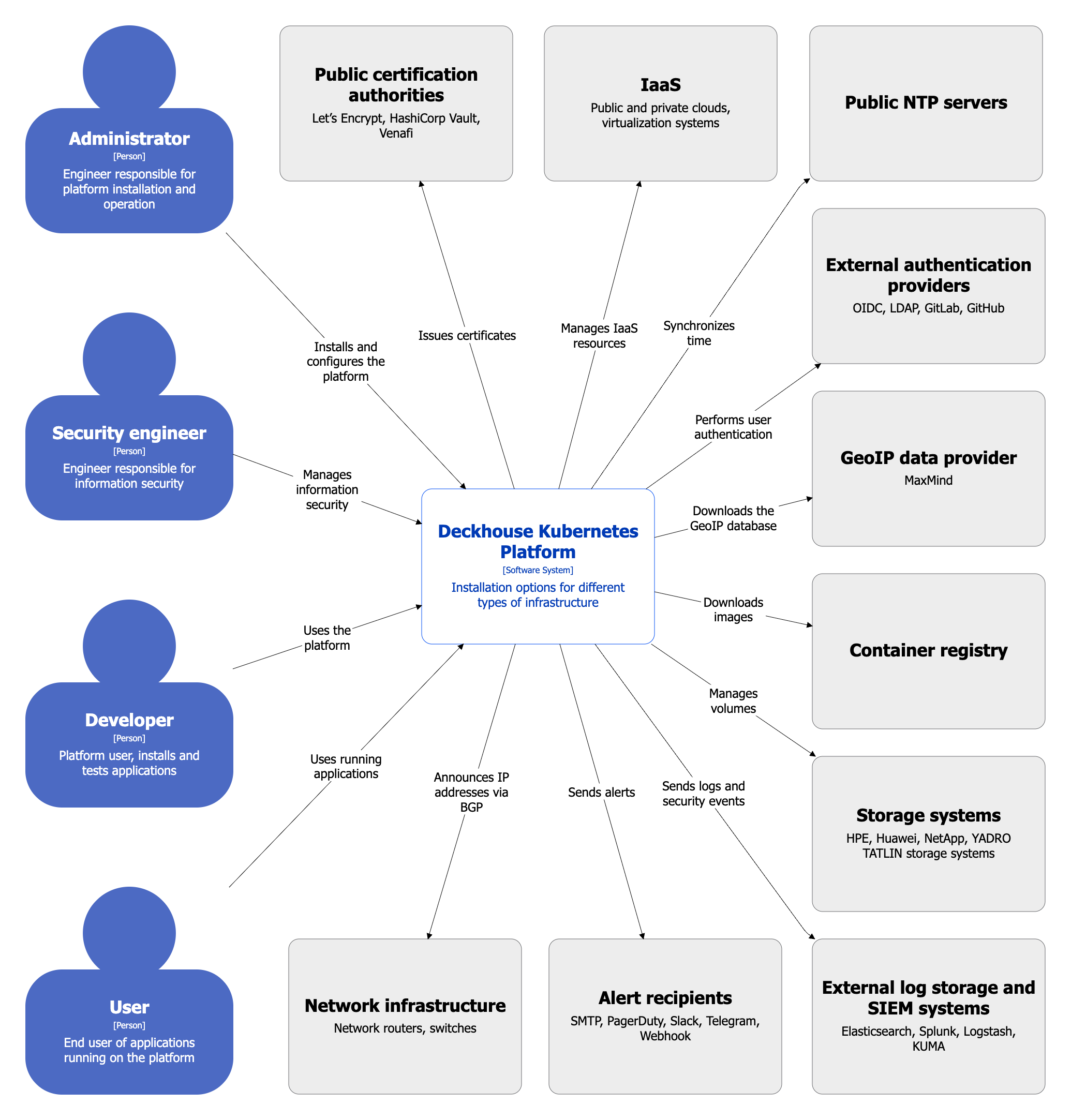
The following roles interact with DKP:
- Administrator: Installs and configures the platform.
- Security Engineer: Manages information security.
- Developer: Uses the platform to deploy and test applications under development.
- User: Uses applications running on the platform.
Interactions with external services are described in the diagrams of subsequent levels.
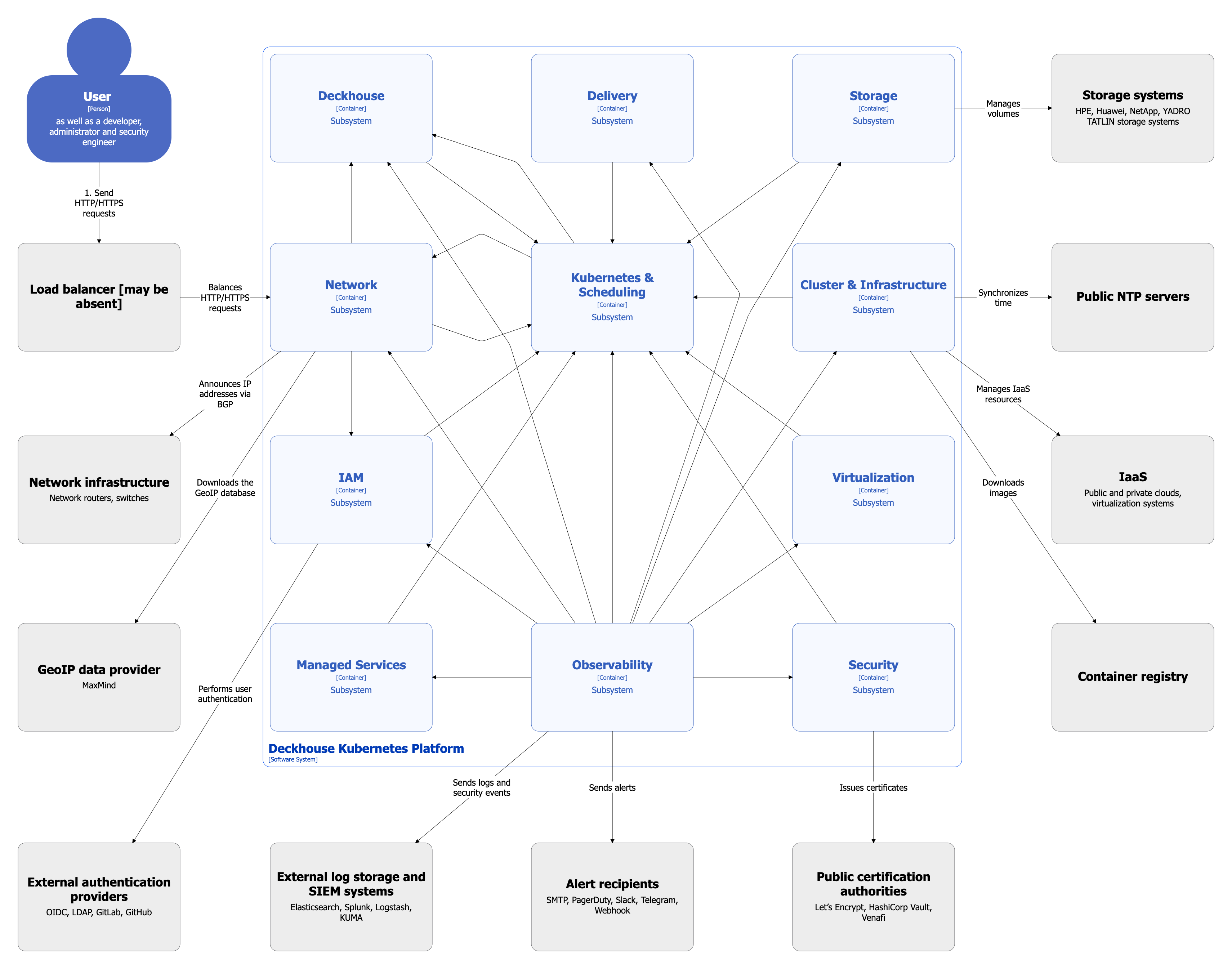
Subsystem diagram
The diagram below shows the DKP subsystems.
Relationships between subsystems are shown in a generalized form and without detailed interactions.
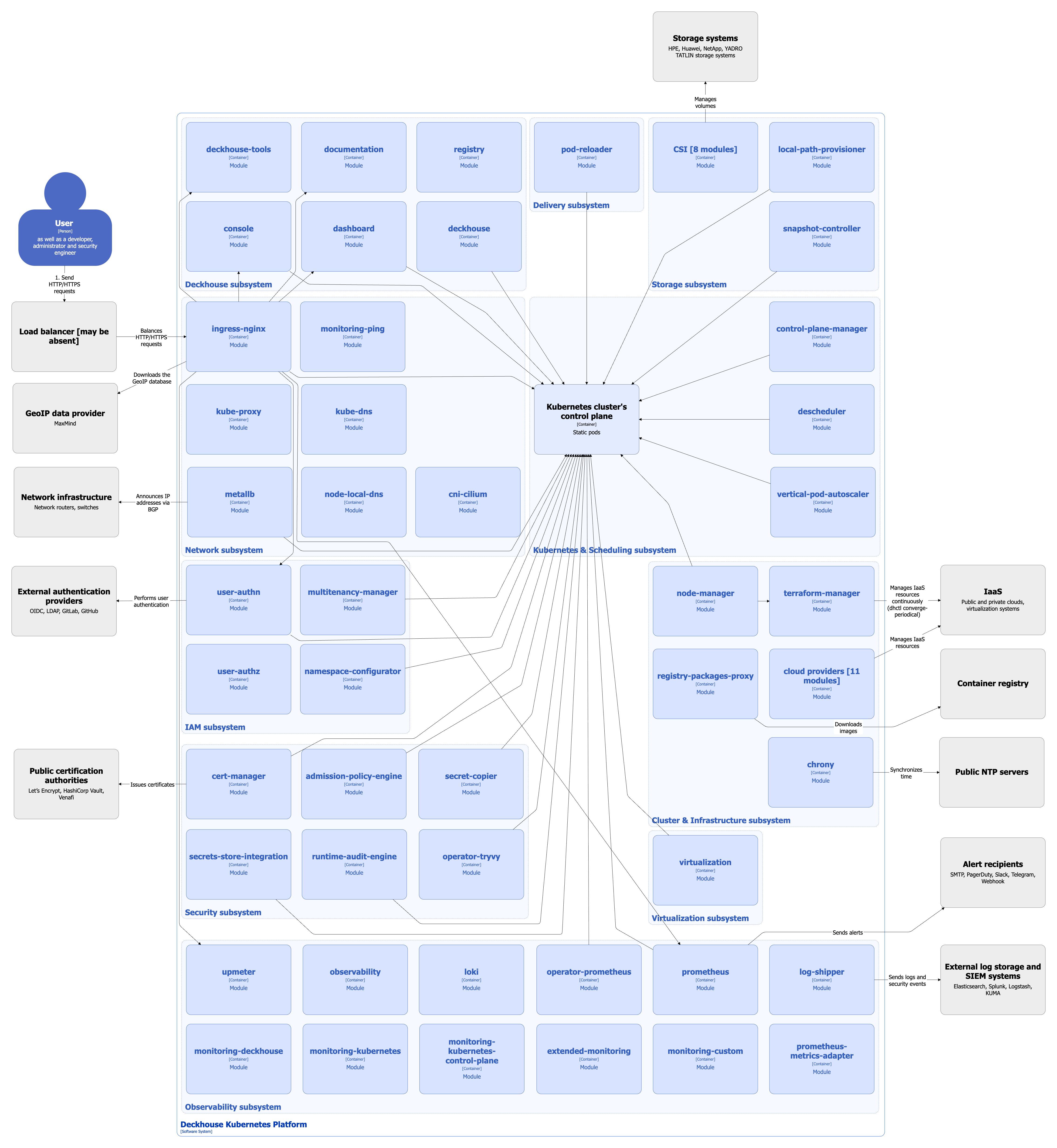
Module diagram
The diagram below shows all modules included in the Default module bundle, as well as the most important additional modules. Modules are grouped by subsystem.
Relationships between modules are shown in a generalized form and without detailed interactions.